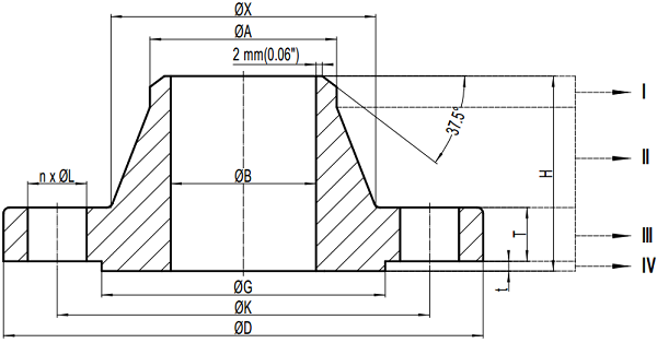
Weld Neck flanges, also know as “WN flanges” or “Welding Neck flanges”, are widely used in oil and gas industry, steam piping and offshore platforms. Sometimes, it is necessary to know the weight of a weld neck flange in piping design. Instead of querying the experimental data from flange manufacturers, theoretical weight can be calculated directly. The weight calculation of weld neck flanges is based on the geometrical or mathematical modeling of the flange.
The typical drawing of weld neck flanges

The typical drawing is for weld neck flanges in accordance with ASME B16.5. The welding end is furnished with beveling for wall thickness from 5 mm to 22 mm (inclusive). And the flange has raised face (RF).
All the dimensions are covered by the standard specification: H – the overall length through hub of weld neck flanges; T – minimum thickness of the flange; t – the height of raised face(2mm for Class 150 and 300, 7mm for Class 400 600, 900, 1500 and 2500); D – outside diameter of the flange; K – diameter of bolt circle; G – outside diameter of the raised face; B – bore diameter of weld neck flanges which is in accordance with ASME B36.10; A – hub diameter at the beginning of chamfer of welding neck flanges; X- root diameter of the hub; n – number of bolts; L – diameter of bolt holes.
Mathematical modeling for weight calculation of weld neck flanges
As illustrated in above drawing, geometrically the weld neck flange can be divided into 4 parts.
Part I can be treated as a short length of pipe. According to ASME B16.5, the straight length is furnished in 10 mm. Hence the weight of Part I can be calculated by using the weight-calculation formula of pipe:
W1 = 0.0246615 * (A – Tk) * Tk * 0.01 Tk – wall thickness of the mating pipe.
Part II can be treated as a truncated cone deducted by a cylinder. Its weight can be calculated as:
W2 = {1/3 * π * (H – T – t – 0.01) * [(X/2)2 + (A/2)2 + X*A/4)] – 1/4 * π * B2 * (H – T – t – 0.01)} * ρ
Part III is a cylinder deducted by several small cylinders(bolt holes and bore):
W3 = 1/4 * π * (D2 – B2 – n*L2) * T * ρ
Part IV, the raised face, can be treated as a cylinder deducted by another cylinder(bore):
W4 = 1/4 * π * (G2 – B2) * t * ρ
The total weight of the weld neck flange is W = W1 + W2 + W3 + W4