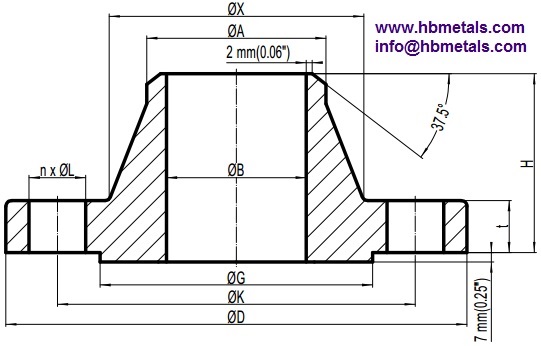
Technical drawing of ASME B16.5 weld neck flanges 400LB.

Dimension and weight specifications of ASME B16.5 Weld Neck flanges 400LB.
| NPS | D inch mm | K inch mm | G inch mm | B inch mm | A inch mm | X inch mm | n | L inch | t inch mm | H inch mm | Wt. lbs kgs |
|---|---|---|---|---|---|---|---|---|---|---|---|
| 1/2" | 3.75 95 | 2.62 66.7 | 1.38 34.9 | - | 0.84 21.3 | 1.50 38 | 4 | 5/8 | 0.56 14.3 | 2.06 52 | 1.90 0.87 |
| 3/4" | 4.62 115 | 3.25 82.6 | 1.69 42.9 | - | 1.05 26.7 | 1.88 48 | 4 | 3/4 | 0.62 15.9 | 2.25 57 | 3.20 1.45 |
| 1" | 4.88 125 | 3.50 88.9 | 2.00 50.8 | - | 1.32 33.4 | 2.12 54 | 4 | 3/4 | 0.69 17.5 | 2.44 62 | 3.90 1.76 |
| 1-1/4" | 5.25 135 | 3.88 98.4 | 2.50 63.5 | - | 1.66 42.2 | 2.50 64 | 4 | 3/4 | 0.81 20.7 | 2.62 67 | 5.50 2.49 |
| 1-1/2" | 6.12 155 | 4.50 114.3 | 2.88 73.0 | - | 1.90 48.3 | 2.75 70 | 4 | 7/8 | 0.88 22.3 | 2.75 70 | 7.70 3.49 |
| 2" | 6.50 165 | 5.00 127.0 | 3.62 92.1 | - | 2.39 60.3 | 3.31 84 | 8 | 3/4 | 1.00 25.4 | 2.88 73 | 9.60 4.36 |
| 2-1/2" | 7.50 190 | 5.88 149.2 | 4.12 104.8 | - | 2.88 73.0 | 3.94 100 | 8 | 7/8 | 1.12 28.6 | 3.12 79 | 14.2 6.43 |
| 3" | 8.25 210 | 6.62 168.3 | 5.00 127.0 | - | 3.50 88.9 | 4.62 117 | 8 | 7/8 | 1.25 31.8 | 3.25 83 | 18.8 8.53 |
| 3-1/2" | 9.00 230 | 7.25 184.2 | 5.50 139.7 | - | 4.00 101.6 | 5.25 133 | 8 | 1 | 1.38 35.0 | 3.38 86 | 23.6 10.7 |
| 4" | 10.00 255 | 7.88 200.0 | 6.19 157.2 | - | 4.50 114.3 | 5.75 146 | 8 | 1 | 1.38 35.0 | 3.50 89 | 28.2 12.8 |
| 5" | 11.00 280 | 9.25 235.0 | 7.31 185.7 | - | 5.56 141.3 | 7.00 178 | 8 | 1 | 1.50 38.1 | 4.00 102 | 37.2 16.9 |
| 6" | 12.50 320 | 10.62 269.9 | 8.50 215.9 | - | 6.63 168.3 | 8.12 206 | 12 | 1 | 1.62 41.3 | 4.06 103 | 48.5 22.0 |
| 8" | 15.00 380 | 13.00 330.0 | 10.62 269.9 | - | 8.63 219.1 | 10.25 260 | 12 | 1-1/8 | 1.88 47.7 | 4.62 117 | 76.4 34.7 |
| 10" | 17.50 445 | 15.25 387.4 | 12.75 323.8 | - | 10.75 273.0 | 12.62 321 | 16 | 1-1/4 | 2.12 54.0 | 4.88 124 | 107 48.5 |
| 12“ | 20.50 520 | 17.75 450.8 | 15.00 381.0 | - | 12.75 323.8 | 14.75 375 | 16 | 1-3/8 | 2.25 57.2 | 5.38 137 | 153 69.6 |
| 14” | 23.00 585 | 20.25 514.4 | 16.25 412.8 | - | 14.00 355.6 | 16.75 425 | 20 | 1-3/8 | 2.38 60.4 | 5.88 149 | 210 95.5 |
| 16“ | 25.50 650 | 22.50 571.5 | 18.50 469.9 | - | 16.00 406.4 | 19.00 483 | 20 | 1-1/2 | 2.50 63.5 | 6.00 152 | 260 118 |
| 18” | 28.00 710 | 24.75 628.6 | 21.00 533.4 | - | 18.00 457.0 | 21.00 533 | 24 | 1-1/2 | 2.62 66.7 | 6.50 165 | 319 145 |
| 20“ | 30.50 775 | 27.00 685.8 | 23.00 584.2 | - | 20.00 508.0 | 23.12 587 | 24 | 1-5/8 | 2.75 69.9 | 6.62 168 | 383 174 |
| 24” | 36.00 915 | 32.00 812.8 | 27.25 692.2 | - | 24.00 610.0 | 27.62 702 | 24 | 1-7/8 | 3.00 76.2 | 6.88 175 | 553 251 |
(1) 400LB refers to Class 400 which is one of the pressure ratings stipulated by ASME B16.5. For dimensional denotation of D, K, G, t, H, A, X, n and L, please reference WN flanges Class 150. The welding end and flange facing(usually RF or RTJ) shall be furnished in accordance with ASME B16.5.
(2) The raised face of weld neck flanges 400LB shall be furnished with a height of 7 mm. All dimensions are provided in both metric and imperial units except for the bolt hole dimensions. Each value of the two systems shall be used separately. The bore diameter B shall be specified by the purchaser. Sizes from NPS 1/2 to NPS 3-1/2 has exactly the same dimensions as that of weld neck flanges 600LB (Class 600).